Topic outline
-
Occupation Name : Electrical Installation and Maintenance ( NTVQF Level-1 )
Civil Construction Sector
Unit Of Competency : Perform Circuit Connection
Unit Code : CONEIM1004A2
Nominal Hours : 20 hours
Unit Descriptor:
This unit covers the knowledge, skills and attitudes required to perform circuit connection. It includes preparing for works, practicing series circuit connection, practicing parallel circuit connection, practicing series and parallel (mixed) circuit connection and maintaining workplace, tools, equipment and materials.
Learning Outcomes :
-
LO-1 : At the end of the session the learner will be able to Perform two lamp control by series circuit with one SPST switch according to industry standard with one hour.
-
LO -2 : At the end of the session the learner will be able to Perform two lamp control by parallel circuit with two SPST switch according to industry standard with two hours.
-
LO -3 : At the end of the session the learner will be able to Perform four lamp control by series and Parallel (Mixed) circuit with one SPST switch according to industry standard with three hours.
Training mode:
1. Online Course : 1 week.
2. Face to Face : 1 Week
Mentors Name :
Md. Jahangir Alam Tarafder ( Shamol )
Trainer:

Rasida Akter
Electrical Installation and Maintenance
ILO Skills-21 Project
Khulna Mohila Polytechnic Institute
-
If you have any query, please write.
-
-

-
If you have any query, please write.
-
-
The Structure of the course :
Only Online Course
Or
Blended Course
In addition to the online course . Physical demonstration is mandatory for this course , so i should go for Blended Course.
Lets go for 1 weeks of online course and 1 weeks of face to face training ( Blended Course ) .
Total Course : 2 Weeks
Online Course : 1 Weeks ( 3 days one weeks for 1 hours ) ( Saturday , Monday, Thursday )
Face to Face : 1 Weeks { 6 days is daily 4 hours}
-
If you have any query, please write.
-
Perform Circuit Connection:
-
-
If you have any query, please write.
-
-
-
If you have any query, please write.
-
-
Materials
-
If you have any query, please write.
-
-
Elements of Competency-01: Practice series circuit connection.
Task-01: perform two lamp control by series circuit with one SPST switch.
Learning Outcomes-01:
At the end of the session the learner will be able to perform two lamp control by series circuit with one SPST switch according to as per industry standard with in one hours.
Discussion :
Introduction to Electrical Circuits:
The interconnection of various electric elements in a prescribed manner comprises as an electric circuit in order to perform a desired function. The electric elements include controlled and uncontrolled source of energy, resistors, capacitors, inductors, etc. Analysis of electric circuits refers to computations required to determine the unknown quantities such as voltage, current and power associated with one or more elements in the circuit. To contribute to the solution of engineering problems one must acquire the basic knowledge of electric circuit analysis and laws.
Series Circuit :
A series circuit comprises a path along which the whole current flows through each component.

Series Circuit Definition:
Resistors are stated to be in series configuration once they are linked in such a way that there is ONLY one path for current flow which means that the current stays the same in all parts of the series circuit.
Wire :
A wire is a long thin piece of metal that is used to fasten things or to carry electric current. ... If you wire something such as a building or piece of equipment, you put wires inside it so that electricity or signals can pass into or through it.


Cable :
A cable is a thick wire, or a group of wires inside a rubber or plastic covering, which is used to carry electricity or electronic signals. ... Cable is used to refer to television systems in which the signals are sent along underground wires rather than by radio waves.


Characteristics of series circuit:

The PPE, Materials, Instrument, Hand tools required to series circuit connection are given below:
PPE: Safety Apron, Safety Helmet, Safety goggles, Mask, Safety Hand gloves, Safety shoe.
Hand Tools : Hammer, Cutting pliers, Combination pliers, Wire striper, Neon tester, Screw driver (flat, star and connecting), Electrician knife , Hack saw blade, Tri-Square .
Measuring Instrument : Analog / Digital Multi meter.
Materials: Bulb, Fuse , SPST Switch ,1.3 Rm Wire , Channel 3/4ʺ, Screw { 1/2ʺ, 3/4ʺ, 1 (1/2)ʺ }, Batten Holder, Junction box, Switch board 1 point.
Demonstration :
Practice Activity / Procedure :
-
Step -1 : Follow OSH.
-
Step -2 : PPE is collected and worn as per job requirement.
-
Step -3 : Workplace is prepared as per job requirement.
-
Step -4 : Tools, materials and drawing are collected as per job requirement.
-
Step -5 : Circuit materials are placed on the board.
-
Step -6 : Circuit accessories are fitted and connected using flexible wire as per drawing.
-
Step -7 : Circuit connection is checked according to the drawing.
-
Step -8 : Electrical circuit connection is checked using series lamp.
-
Step -9 : Series circuit is tested with connected power supply.
-
Step -10 : Tools and equipment are cleaned and stored as per manufacturer's recommendation in appropriate location.
Series circuit diagram:

-
Series Circuit Connection Video:
-
-
Elements of Competency-02: Practice Parallel circuit connection.
Task-02: perform two lamp control by parallel circuit with two SPST switch
Learning Outcomes-02:
At the end of the session the learner will be able to perform two lamp control by parallel circuit with two SPST switch according to as per industry standard with in two hours.
Discussion :
Parallel Circuit :
A parallel circuit has branches that divide the current so that just a part of it passes through each branch. On the other hand, the essential concept of a “parallel” connection is that all components are linked across each other’s leads. No matter how many components are connected in a purely parallel circuit, there are never more than two sets of electrically common points. There are numerous current flow pathways, but only one voltage exists across all components. Parallel circuits allow charge to pass across two or more routes due to these characteristics, making them a popular choice for use in houses and electrical equipment with a reliable and efficient power supply. When a component of a circuit is damaged or destroyed, electricity can flow via other parts of the circuit, and power can be distributed evenly over multiple buildings. A diagram and an example of a parallel circuit can be used to explain these features.


Parallel Circuit Definition:
Resistors are said to be connected in parallel when the same voltage appears across every component. With different resistance values, different currents flow through each resistor. The total current taken from the supply is the sum of all the individual resistor currents. The equivalent resistance of a parallel resistor circuit is most easily calculated by using the reciprocal of each individual resistor value.
Characteristics of Parallel circuit:

The PPE, Materials, Instrument, Hand tools required to parallel circuit connection are given below:
PPE: Safety Apron, Safety Helmet, Safety goggles, Mask, Safety Hand gloves, Safety shoe.
Hand Tools : Hammer, Cutting pliers, Combination pliers, Wire striper, Neon tester, Screw driver (flat, star and connecting), Electrician knife , Hack saw blade, Tri-Square .
Measuring Instrument : Analog / Digital Multi meter.
Materials: Bulb, Fuse , SPST Switch ,1.3 Rm Wire , Channel 3/4ʺ, Screw { 1/2ʺ, 3/4ʺ, 1 (1/2)ʺ }, Batten Holder, Junction box, Switch board 1 point.
Demonstration :
Practice Activity / Procedure :
-
Step -1 : Follow OSH.
-
Step -2 : PPE is collected and worn as per job requirement.
-
Step -3 : Workplace is prepared as per job requirement.
-
Step -4 : Tools, materials and drawing are collected as per job requirement.
-
Step -5 : Circuit materials are placed on the board.
-
Step -6 : Circuit accessories are fitted and connected using flexible wire as per drawing.
-
Step -7 : Circuit connection is checked according to the drawing.
-
Step -8 : Electrical circuit connection is checked using series lamp.
-
Step -9 : Parallel circuit is tested with connected power supply.
-
Step -10 : Tools and equipment are cleaned and stored as per manufacturer's recommendation in appropriate location.
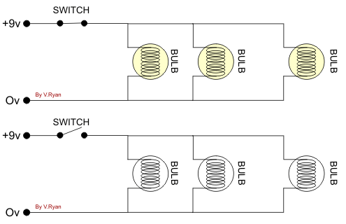
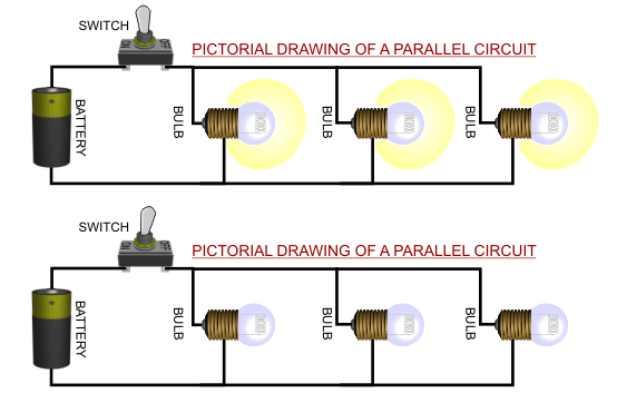
Parallel circuit diagram:
-
-
Elements of Competency-03: Practice Series and Parallel (Mixed) circuit connection.
Task-03: perform four lamp control by series and parallel (Mixed) circuit with one SPST switch.
Learning Outcomes-03:
At the end of the session the learner will be able to perform four lamp control by series and parallel (Mixed) circuit with one SPST switch according to as per industry standard with in three hours.
Discussion :
Series and Parallel (Mixed) Circuit :
In a series circuit, all components are connected end-to-end, forming a single path for electrons to flow. In a parallel circuit, all components are connected across each other, forming exactly two sets of electrically common points.


Series and Parallel (Mixed) Circuit Definition:
In a parallel circuit, the voltage across each of the components is the same, and the total current is the sum of the currents flowing through each component. ... In a series circuit, every device must function for the circuit to be complete. If one bulb burns out in a series circuit, the entire circuit is broken.
Characteristics of Series and Parallel (Mixed) circuit:
The PPE, Materials, Instrument, Hand tools required to parallel circuit connection are given below:
PPE: Safety Apron, Safety Helmet, Safety goggles, Mask, Safety Hand gloves, Safety shoe.
Hand Tools : Hammer, Cutting pliers, Combination pliers, Wire striper, Neon tester, Screw driver (flat, star and connecting), Electrician knife , Hack saw blade, Tri-Square .
Measuring Instrument : Analog / Digital Multi meter.
Materials: Bulb, Fuse , SPST Switch , 1.3 Rm Wire , Channel 3/4ʺ, Screw { 1/2ʺ, 3/4ʺ, 1 (1/2)ʺ }, Batten Holder, Junction box, Switch board 2 point.
Demonstration :
Practice Activity / Procedure :
-
Step -1 : Follow OSH.
-
Step -2 : PPE is collected and worn as per job requirement.
-
Step -3 : Workplace is prepared as per job requirement.
-
Step -4 : Tools, materials and drawing are collected as per job requirement.
-
Step -5 : Circuit materials are placed on the board.
-
Step -6 : Circuit accessories are fitted and connected using flexible wire as per drawing.
-
Step -7 : Circuit connection is checked according to the drawing.
-
Step -8 : Electrical circuit connection is checked using series lamp.
-
Step -9 : Series and Parallel (Mixed) circuit is tested with connected power supply.
-
Step -10 : Tools and equipment are cleaned and stored as per manufacturer's recommendation in appropriate location.
Series and Parallel (Mixed) circuit diagram:


-
Mixed Circuit Connection Video:
-